Duct Bank Ampacity
A Underground Duct Bank Cable Ampacity and Thermal Calculation Study will determine if your duct bank design will support the loads and not cause conductor over heating. We use ETAP’s state-of-the-art Cable Thermal Software Module and accurately determine the ampacity and thermal limitations of different underground raceways and duct banks.This program is especially beneficial for our clients who are designing duct banks that deviate from the NEC© duct bank tables.
Many times, design engineers and contractors cannot design and install underground duct banks as shown in the 2011 NEC© Tables 310.15(B)(16) as well as Figure 310.60 & Tables 310.60(C)(77) to 310.60.(C)(86). Sections 310.16(A)(1) and 310.60.(B) states that the ampacities shall be permitted to be determined by the tables or under engineering supervision, as provided in 310.60(C) and (D). Many AHJs will require thermal and ampacity calculations performed and stamped by Professional Engineers.
Cable derating analysis is an important part of power system design and analysis. Our study determines the proper size of cables to carry the specified loads. For an existing system, the cable thermal analysis software examines cable temperatures and determines their ampacity.
The ETAP cable thermal analysis program provides five types of calculations for cable derating analysis, namely, steady-state temperature calculation, uniform-ampacity cable ampacity calculation, uniform-temperature cable ampacity calculation, cable sizing, and transient temperature calculation. The steady-state temperature calculation is based on the IEC 60287 or the NEC© accepted Neher-McGrath method.
More information about the ETAP program can be found at
http://etap.com/cable-systems/underground-thermal-analysis.htm
Our report will include the following:
Introduction
Executive Summary
Data Input of physical characteristics of the cables, soil, and duct bank parameters
Data output flagging critical and marginal cable temperatures.
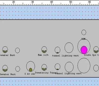
Graphical Display of the Raceway Results
The benefits of this study include:
Design time savings
Material cost savings by determining the minimum size of conductors to support the anticipated loads